Open vehicle or closed tanker?
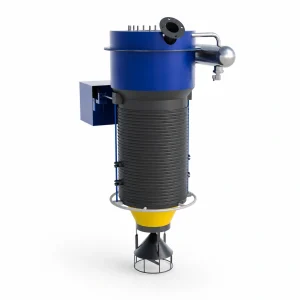
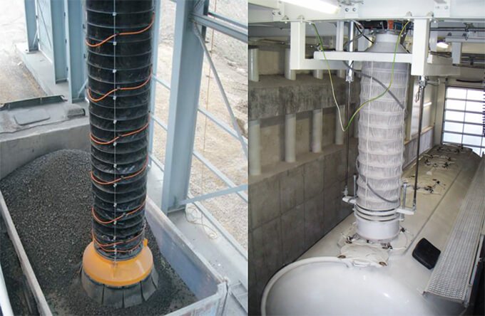
With an open body, the loading point moves relative to the rising material pile. A suitable skirt and controlled bellow movement help contain the falling stream. At a tanker hatch, the end cone or connection must match the opening and allow displaced air to be handled.
State vehicle types, hatch diameters, parking tolerance, lowest and highest filling positions and required stroke. One end fitting should not be assumed to serve both applications.
Separate material delivery from air extraction
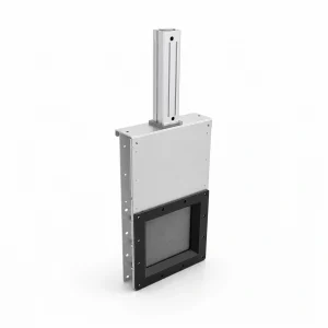
The upstream gate or feeder controls product supply. A slide gate valve may provide isolation, while a cement screw conveyor may supply material in a suitable cement application; their sizing and control must match the loading duty. The bellow guides the falling material; the extraction circuit captures dusty air. These are separate duties that must be coordinated.
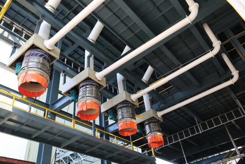
Confirm where extracted air goes and how the filter returns or collects dust. Poor extraction, a damaged sleeve or an unsuitable vehicle connection can each cause visible emissions. Record whether dust appears at initial feed, during steady loading or when the unit disconnects, and identify the location of the escape. Include the loading rate and available extraction or filter readings; these observations help distinguish the connection, sleeve and extraction duties. See the filter pressure-drop and maintenance guide when the extraction filter is part of the investigation.
Define the loading sequence
- Position the vehicle and establish the intended loading connection.
- Confirm the required extraction and equipment-ready signals before material feed.
- Use level and position feedback appropriate to open or closed loading.
- Stop material supply before disconnecting; allow the specified clearing and extraction sequence.
Retraction and vehicle departure need a defined release sequence. The exact interlocks belong to the installation design.
For a quote
Choose for the material and daily duty
Minerals and cement can impose abrasion and high dust loads. Food and feed require suitable contact materials and cleaning. Chemicals may need compatibility and dust-hazard provisions. Temperature, particle size and loading frequency affect sleeve, cone and wear-part selection.
Send material data, target loading rate, vehicle photographs, opening dimensions, available headroom and extraction details. Include the required time per vehicle and any product changes. Provide a dimensioned sketch showing the fixed mounting point, highest and lowest vehicle openings, retracted clearance and required operating reach. Confirm the mounting connection and available space for maintenance.
For an existing installation, include the equipment label and describe where and when dust appears. For a general introduction to the equipment, read what a loading bellow does and how it works.